
TM 5-2410-240-23-2
0126
INSTALLATION CONTINUED
N OT E
Install electrical connectors and tiedown straps as noted during removal.
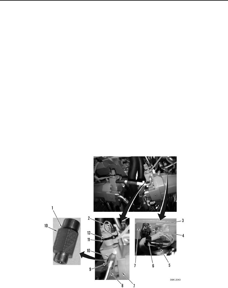
10. Connect harness (Figure 5, Item 2) on solenoid (Figure 5, Item 11).
11. Install new tiedown strap (Figure 5, Item 12) on harness (Figure 5, Item 2) and solenoid (Figure 5, Item 11).
N OT E
Steps 12 through 14 apply to right drive motor only.
Remove all caps or plugs from hydraulic hoses and fittings and install hoses as noted
during removal.
12. Install two new O-rings (Figure 5, Item 1) on fitting (Figure 5, Item 10).
13. Install fitting (Figure 5, Item 10) on drive motor (Figure 5, Item 7).
14. Connect hose (Figure 5, Item 8) on fitting (Figure 5, Item 10) and tighten nut (Figure 5, Item 9).
N OT E
Install electrical connectors and tiedown straps as noted during removal.
15. Install sensor (Figure 5, Item 4) and two bolts (Figure 5, Item 3) on drive motor (Figure 5, Item 7).
16. Connect harness (Figure 5, Item 5) on sensor (Figure 5, Item 4).
17. Install new tiedown strap (Figure 5, Item 6) on harness (Figure 5, Item 5) and sensor (Figure 5, Item 4).
Figure 5. Sensor and Solenoid on Drive Motor.
0126