
TM 5-2410-240-23-2
0159
WINCH PUMP CHARGE HOSES AND TUBES REMOVAL
000159
1. Remove batteries (WP 0142).
2. Remove rear cab floor plates (WP 0205).
3. Remove manifold as described in this work package. Refer to Hydraulic System Supply Hoses and Manifold
Removal.
N OT E
Tag and mark hoses and fittings to aid installation.
Note location of tiedown straps to aid installation.
Use a container to catch any fluid that may drain from hoses or system. Dispose of fluid
IAW local policy and ordinances. Ensure all spills are cleaned up.
Cap or plug hoses and fittings.
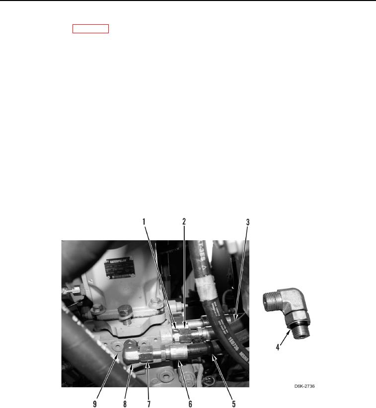
4. Loosen tube nut (Figure 4, Item 7) and disconnect hose (Figure 4, Item 6) from fitting (Figure 4, Item 8).
5. Loosen tube nut (Figure 4, Item 2) and disconnect hose (Figure 4, Item 3) from fitting (Figure 4, Item 1).
6. Remove two fittings (Figure 4, Items 1 and 8) from winch piston pump (Figure 4, Item 9).
7. Remove four O-rings (Figure 4, Item 4) from two fittings (Figure 4, Items 1 and 8). Discard O-rings.
8. Remove tiedown straps (Figure 4, Item 5) from two hoses (Figure 4, Items 6 and 3). Discard tiedown straps.
Figure 4. Hoses and Fittings on Winch Piston Pump.
0159