
TM 5-2410-240-23-2
0159
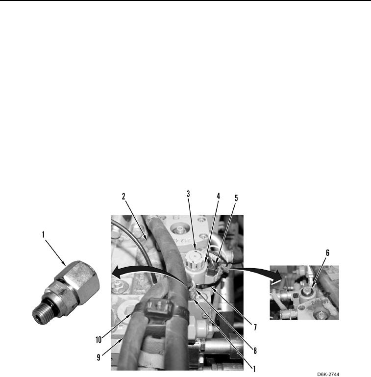
WINCH PRESSURE AND RETURN HOSE AND TUBES REMOVAL CONTINUED
N OT E
Tag and mark electrical connectors, hose, and fitting to aid installation.
Note location of tiedown straps to aid installation.
Cap or plug hose and fitting.
13. Remove tiedown strap (Figure 9, Item 7) from harness (Figure 9, Item 5) and solenoid (Figure 9, Item 4).
Discard tiedown strap.
14. Disconnect harness (Figure 9, Item 5) from solenoid (Figure 9, Item 4).
15. Remove nut (Figure 9, Item 3), O-ring (Figure 9, Item 6), and solenoid (Figure 9, Item 4) from winch piston
pump (Figure 9, Item 2). Discard O-ring.
16. Loosen tube nut (Figure 9, Item 8) and disconnect hose (Figure 9, Item 9) from fitting (Figure 9, Item 1).
17. Remove fitting (Figure 9, Item 1) from winch piston pump (Figure 9, Item 2).
18. Remove two O-rings (Figure 9, Item 11) from fitting (Figure 9, Item 1). Discard O-rings.
19. Remove tiedown straps (Figure 9, Item 10) from hose (Figure 9, Item 9). Discard tiedown straps.
Figure 9. Hose and Fitting on Winch Piston Pump.
0159