
TM 5-2410-240-23-2
0159
WINCH PRESSURE AND RETURN HOSE AND TUBES REMOVAL CONTINUED
N OT E
Tag and mark hoses and fittings to aid installation.
Note orientation of fittings to aid installation.
Cap or plug hoses and fittings.
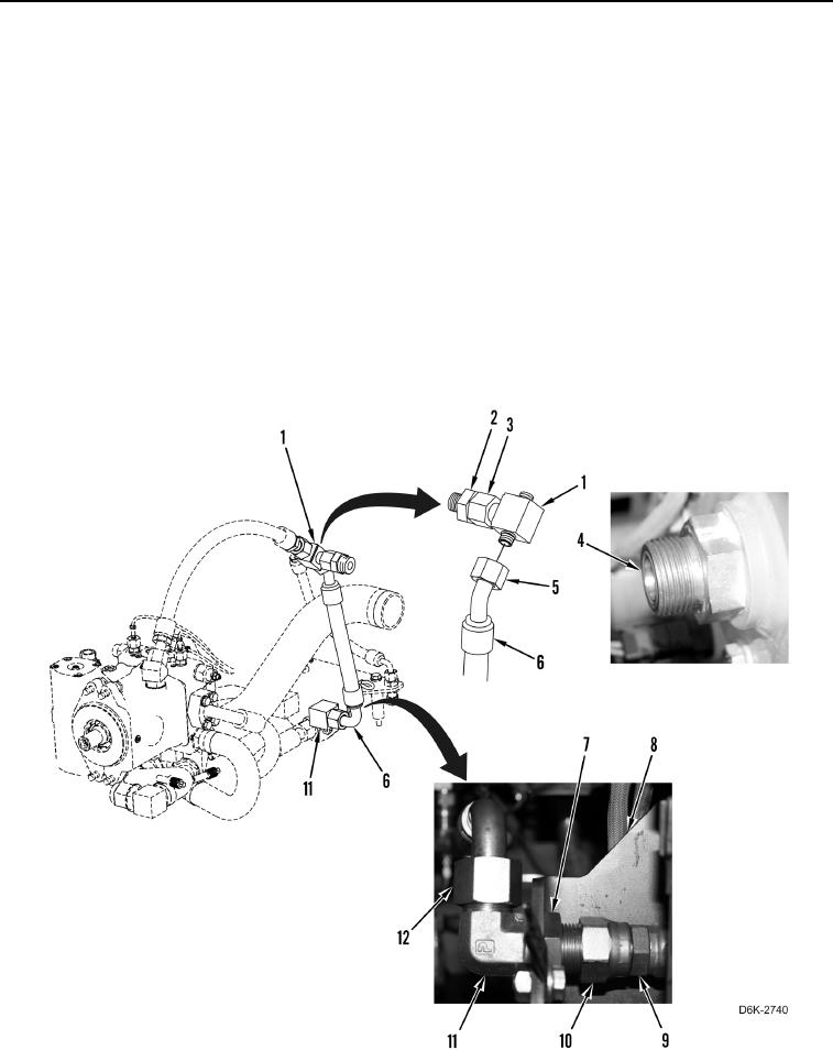
6. Loosen tube nut (Figure 8, Item 12) and disconnect hose (Figure 8, Item 6) from fitting (Figure 8, Item 11).
7. Loosen tube nut (Figure 8, Item 5) and disconnect hose (Figure 8, Item 6) from fitting (Figure 8, Item 1).
Remove hose from machine.
8. Loosen nut (Figure 8, Item 3) and remove fitting (Figure 8, Item 1) from fitting (Figure 8, Item 2).
9. Remove three O-rings (Figure 8, Item 4) from fittings (Figure 8, Items 1 and 2). Discard O-rings.
10. Loosen tube nut (Figure 8, Item 10) and nut (Figure 8, Item 7) and disconnect hose (Figure 8, Item 9) from
fitting (Figure 8, Item 11).
11. Remove nut (Figure 8, Item 7) and fitting (Figure 8, Item 11) from bracket (Figure 8, Item 8).
12. Remove two O-rings (Figure 8, Item 4) from fitting (Figure 8, Item 11). Discard O-rings.
Figure 8. Hoses and Fittings on Hydraulic Tank and Bracket.
0159