
TM 5-2410-240-23-2
0159
WINCH PRESSURE AND RETURN HOSE AND TUBES REMOVAL
000159
1. Remove hydraulic system supply hoses and manifold as described in this work package. Refer to Hydraulic
System Supply Hoses and Manifold Removal.
N OT E
Tag and mark hose and fitting to aid installation.
Note orientation of fitting to aid installation.
Cap or plug hose and fitting.
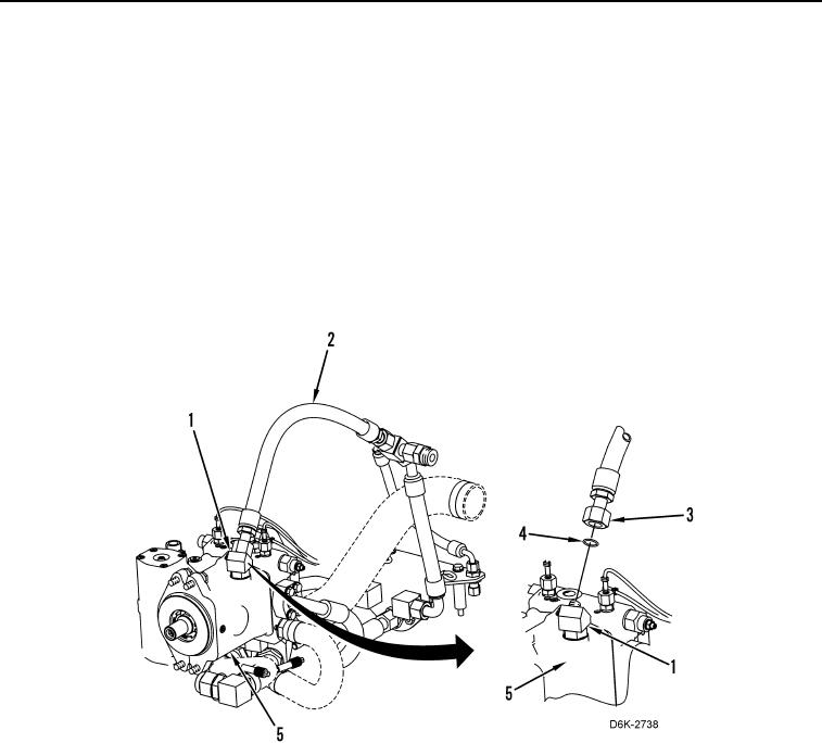
2. Loosen tube nut (Figure 6, Item 3) and disconnect hose (Figure 6, Item 2) from fitting (Figure 6, Item 1).
3. Remove fitting (Figure 6, Item 1) from winch piston pump (Figure 6, Item 5).
4. Remove two O-rings (Figure 6, Item 4) from fitting (Figure 6, Item 1). Discard O-rings.
Figure 6. Hose and Fitting on Winch Piston Pump.
0159