
TM 5-2410-240-23-2
0159
WINCH PRESSURE AND RETURN HOSE AND TUBES INSTALLATION CONTINUED
N OT E
Remove caps or plugs from hose and fitting.
Install hose and fitting as noted during removal.
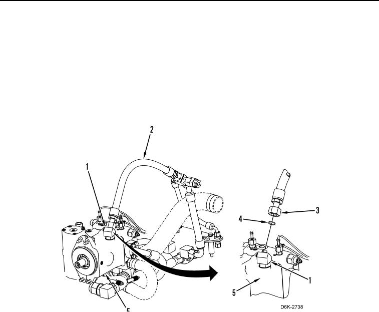
48. Lubricate two new O-rings (Figure 19, Item 4) with lubricating oil.
49. Install two new O-rings (Figure 19, Item 4) on fitting (Figure 19, Item 1).
50. Install fitting (Figure 19, Item 1) on winch piston pump (Figure 19, Item 5).
51. Connect hose (Figure 19, Item 2) to fitting (Figure 19, Item 1) and tighten tube nut (Figure 19, Item 3).
Figure 19. Hose and Fitting on Winch Piston Pump.
0159
52. Install manifold and hydraulic system supply hoses as described in this work package. Refer to Hydraulic
System Supply Hoses and Manifold Installation.
END OF TASK