
TM 5-2410-240-23-2
0159
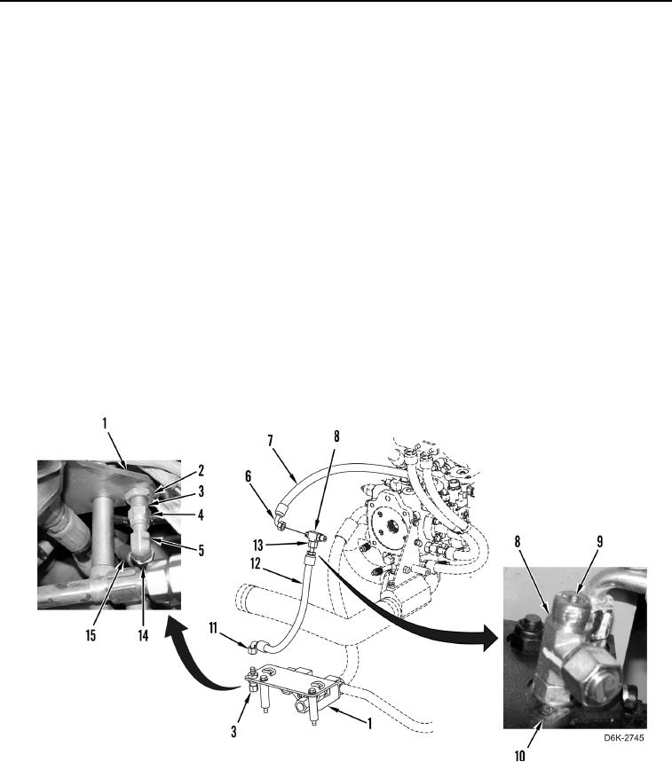
WINCH PRESSURE AND RETURN HOSE AND TUBES INSTALLATION CONTINUED
N OT E
Remove caps or plugs from hoses and fittings.
Install hoses and fittings as noted during removal.
17. Lubricate two new O-rings (Figure 15, Item 9) with lubricating oil.
18. Install two new O-rings (Figure 15, Item 9) on fitting (Figure 15, Item 3).
19. Install fitting (Figure 15, Item 3) and nut (Figure 15, Item 2) on bracket (Figure 15, Item 1).
20. Lubricate new O-ring (Figure 15, Item 9) with lubricating oil.
21. Install new O-ring (Figure 15, Item 9) to fitting (Figure 15, Item 5).
22. Install fitting (Figure 15, Item 5) on fitting (Figure 15, Item 3) and tighten nut (Figure 15, Item 4).
23. Connect hose (Figure 15, Item 15) to fitting (Figure 15, Item 5) and tighten tube nut (Figure 15, Item 14).
24. Lubricate three new O-rings (Figure 15, Item 9) with lubricating oil.
25. Install three new O-rings (Figure 15, Item 9) on fitting (Figure 15, Item 8).
26. Install fitting (Figure 15, Item 8) on valve bank (Figure 15, Item 10).
27. Connect hose (Figure 15, Item 12) to fitting (Figure 15, Item 8) and tighten tube nut (Figure 15, Item 13).
28. Connect hose (Figure 15, Item 12) to fitting (Figure 15, Item 3) and tighten tube nut (Figure 15, Item 11).
29. Connect hose (Figure 15, Item 7) to fitting (Figure 15, Item 8) and tighten tube nut (Figure 15, Item 6).
Figure 15. Hoses and Fittings on Valve Bank and Bracket.
0159