
TM 5-2410-240-23-2
0171
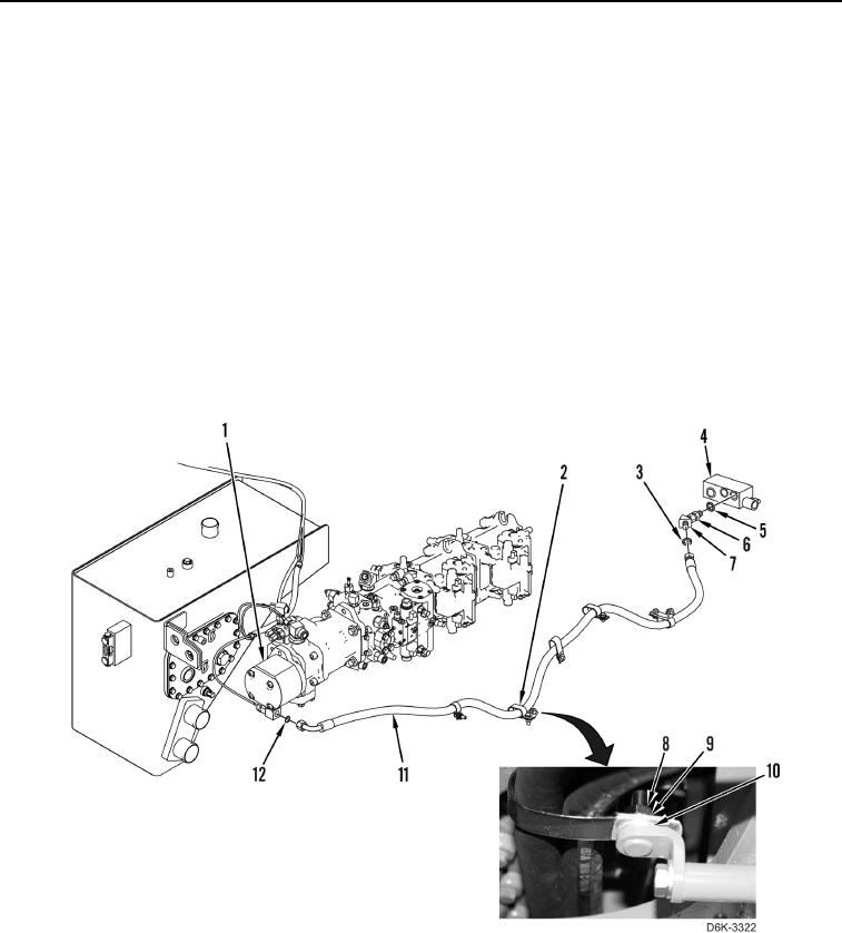
HOSES REMOVAL CONTINUED
9. Disconnect hose (Figure 4, Item 11) and remove O-ring (Figure 4, Item 12) from pump (Figure 4, Item 1).
Discard O-ring.
N OT E
Hose clamps are all removed using the same general method. This procedure covers
removal of one clamp from machine.
Note position of clamps to aid installation.
10. Remove nut (Figure 4, Item 8), washer (Figure 4, Item 9), clamp (Figure 4, Item 2), and spacer (Figure 4,
Item 10) from machine.
11. Disconnect hose (Figure 4, Item 11), and remove O-ring (Figure 4, Item 3) from elbow (Figure 4, Item 7).
Discard O-ring.
12. Loosen nut (Figure 4, Item 6), and remove elbow (Figure 4, Item 7) from demand fan manifold (Figure 4,
Item 4), and remove O-ring (Figure 4, Item 5) from elbow (Figure 4, Item 7). Discard O-ring.
13. Remove hose (Figure 4, Item 11) from machine.
Figure 4. Pump to Demand Fan Manifold.
0171
END OF TASK