
TM 5-2410-240-23-2
0171
DIAGNOSTIC TUBES INSTALLATION
000171
N OT E
Hydraulic hoses and fittings from the test panel to the pump are all installed using the
same general method. This procedure covers installation of one hydraulic hose assembly
on machine.
Install hoses and fittings as noted during removal procedure.
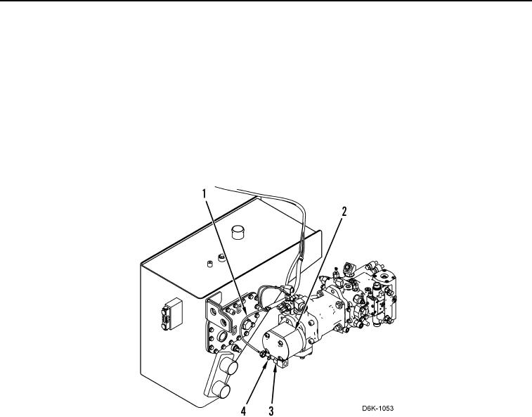
1. Install reducer (Figure 7, Item 3) on pump (Figure 7, Item 2).
2. Install new O-ring (Figure 7, Item 4) on reducer (Figure 7, Item 3) and connect hose (Figure 7, Item 1) to pump
(Figure 7, Item 2).
Figure 7. Pump to Test Panel Hoses.
0171