
TM 5-2410-240-23-2
0171
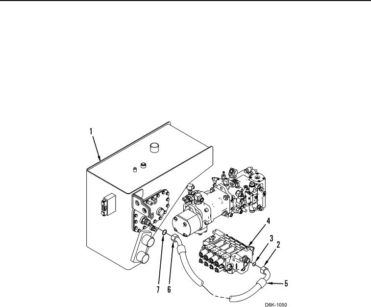
HOSES INSTALLATION CONTINUED
10. Install connector (Figure 11, Item 2) and new O-ring (Figure 11, Item 3) on valve bank (Figure 11, Item 4).
N OT E
Install hoses as noted during removal procedure.
11. Install new O-ring (Figure 11, Item 3) and hose (Figure 11, Item 5) on connector (Figure 11, Item 2).
12. Install new O-ring (Figure 11, Item 7) and check valve (Figure 11, Item 6) on hydraulic tank (Figure 11, Item 1).
13. Install new O-ring (Figure 11, Item 7) and connect hose (Figure 11, Item 5) to check valve (Figure 11, Item 6).
Figure 11. Tank to Valve Bank Hose.
0171