
TM 5-2410-240-23-2
0171
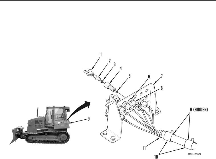
DIAGNOSTIC TUBES INSTALLATION CONTINUED
3. Install 13 new O-rings (Figure 8, Item 5), fittings (Figure 8, Item 4), nuts (Figure 8, Item 6), new O-rings
(Figure 8, Item 3), connectors (Figure 8, Item 2), and dust caps (Figure 8, Item 1) on test panel (Figure 8,
Item 7).
4. Connect 13 hoses (Figure 8, Item 8) to fitting (Figure 8, Item 4).
5. Install two clamps (Figure 8, Item 10) and nuts (Figure 8, Item 9) on hose harness (Figure 8, Item 11).
Figure 8. Test Panel and Hoses.
0171
END OF TASK