
TM 5-2410-240-23-2
0171
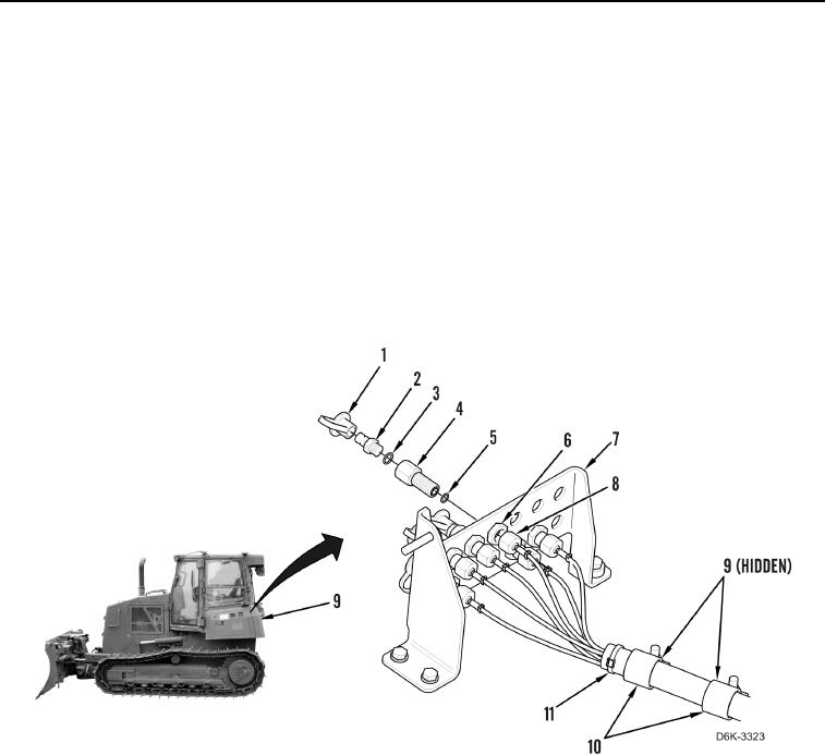
DIAGNOSTIC TUBES REMOVAL
000171
1. Open left rear access door (Figure 5, Item 9).
N OT E
Hydraulic hoses and fittings from the test panel to the pump are all removed using the
same general method. This procedure covers removal of one hydraulic hose assembly
from machine.
Tag all hoses, tubes, and fittings to aid installation.
Note routing of hoses to aid installation.
2. Remove 13 hoses (Figure 5, Item 8) from 13 fittings (Figure 5, Item 4).
3. Remove two nuts (Figure 5, Item 9) and two clamps (Figure 5, Item 10) and position hose harness (Figure 5,
Item 11) aside.
Figure 5. Test Panel and Hoses.
0171
4. Remove 13 dust caps (Figure 5, Item 1), connectors (Figure 5, Item 2), O-rings (Figure 5, Item 3), nuts
(Figure 5, Item 6), fittings (Figure 5, Item 4), and O-rings (Figure 5, Item 5) from test panel (Figure 5, Item 7).
Discard O-rings.