
TM 5-2410-240-23-2
0171
HOSES INSTALLATION CONTINUED
N OT E
Install hoses and fittings as noted during removal procedure.
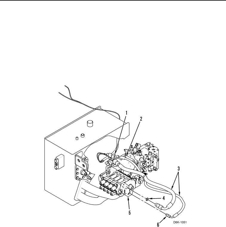
7. Install two connectors (Figure 10, Item 6) and two new O-rings (Figure 10, Item 4) on valve bank (Figure 10,
Item 5).
8. Install two new O-rings (Figure 10, Item 4) on two connectors (Figure 10, Item 6), and connect two hoses
(Figure 10, Item 3) to two connectors (Figure 10, Item 6).
9. Install two new O-rings (Figure 10, Item 1) and connect two hoses (Figure 10, Item 3) to pump (Figure 10,
Item 2).
Figure 10. Pump to Valve Bank Hoses.
0171