
TM 5-2410-240-23-2
0171
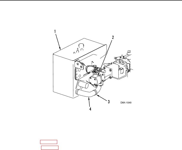
HOSES INSTALLATION CONTINUED
14. Install hose (Figure 12, Item 4) on hydraulic tank (Figure 12, Item 1) and pump (Figure 12, Item 2) and tighten
two clamps (Figure 12, Item 3).
Figure 12. Hydraulic Tank to Pump Hose.
0171
END OF TASK
FOLLOW-ON TASKS
000171
1. Fill hydraulic system (WP 0160).
2. Install bottom guards (WP 0156).
3. Verify correct operation of machine (TM 5-2410-240-10).
END OF TASK
END OF WORK PACKAGE