
2
TM 5-2410-241-23-1
FIELD MAINTENANCE
-
AIR INLET TEMPERATURE SENSOR HARNESS REPLACEMENT
005
4
Removal, Cleaning and Inspection, Installation
INITIAL SETUP
Equipment Condition
Tools and Special Tools
0
0
Tool Kit, General Mechanic's
Machine parked (TM 5-2410-241-10)
0
(WP 0302, Item 65)
0
Drawing Required
0
Materials/Parts
TM 5-2410-24P, Figure 15
0
0
Rag, Wiping (WP 0303, Item 24)
0
Estimated Time to Complete
0
Tag, Marker (WP 0303, Item 34)
0
0.5 Hr
Tiedown Strap (WP 0303, Item 36)
0
0
References
0
WP 0295
0
REMOVAL
00054
N OT E
Note harness routing to aid installation.
Tag and mark all electrical connections to aid installation.
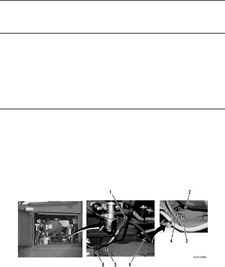
1. Disconnect connector (Figure 1, Item 3) from air inlet temperature sensor (Figure 1, Item 2).
2. Remove tiedown straps (Figure 1, Item 1) from air inlet temperature sensor harness (Figure 1, Item 4). Discard
tiedown strap.
3. Disconnect connector (Figure 1, Item 6) from connector (Figure 1, Item 5).
4. Remove air inlet temperature sensor harness (Figure 1, Item 4) from machine.
Figure 1. Fuel Temperature Sensor Harness.
0054
END OF TASK