
TM 5-2410-241-23-1
0053
NATO SLAVE INSTALLATION CONTINUED
N OT E
Negative cable attaches to right side of NATOslave. Right side of NATO slave faces rear
of machine. Positive cable attaches to left side of NATO slave. Left side of NATO slave
faces front of machine.
Route cables and install electricalconnectors as noted during removal.
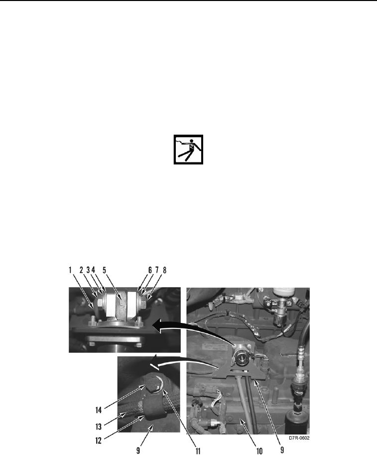
3. Install bracket assembly (Figure 8, Item 9) on engine (Figure 8, Item 10).
4. Install wiring harness (Figure 8, Item 13), clamp (Figure 8, Item 12), two washers (Figure 8, Item 11), and bolts
(Figure 8, Item 14) on bracket assembly (Figure 8, Item 9).
WARN I N G
Plus and minus symbols are stamped in NATO slave near battery cable terminal
connectors. Install NATO slave on bracket so positive terminal connector faces front of
machine and negative terminal connector faces rear of machine. Failure to follow this
warning may result in injury or death to personnel or damage to equipment.
5. Install cable (Figure 8, Item 6), new lockwasher (Figure 8, Item 7) and bolt (Figure 8, Item 8) on NATO slave
(Figure 8, Item 5).
6. Install cable (Figure 8, Item 4), new lockwasher (Figure 8, Item 3) and bolt (Figure 8, Item 2) on NATO slave
(Figure 8, Item 5). Position boot (Figure 8, Item 1) on bolt.
Figure 8. NATO Slave Cables.
0053