
TM 5-2410-241-23-1
0053
NATO SLAVE CABLE INSTALLATION
00053
N OT E
Route cables and install electrical connectors as noted during removal.
1. Position negative cable (Figure 5, Item 4) and positive cable (Figure 5, Item 1) on machine.
2. Install negative cable (Figure 5, Item 4) and nut (Figure 5, Item 3) on starter (Figure 5, Item 5).
3. Install positive cable (Figure 5, Item 1) and nut (Figure 5, Item 2) on starter (Figure 5, Item 5).
N OT E
Negative cable attaches to right side of NATOslave. Right side of NATO slave faces rear
of machine. Positive cable attaches to left side of NATO slave. Left side of NATO slave
faces front of machine.
Tag and mark electrical connectors andnote cable routing to aid installation.
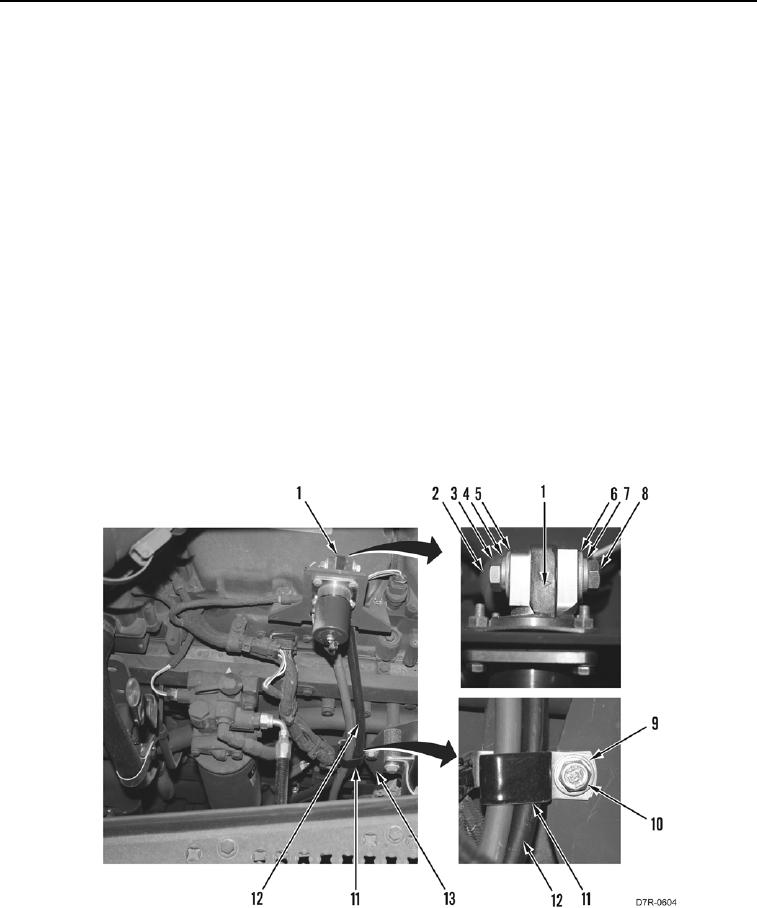
4. Install clamp (Figure 6, Item 11) on two cables (Figure 6, Item 12).
5. Install clamp (Figure 6, Item 11), washer (Figure 6, Item 9) and bolt (Figure 6, Item 10) on engine (Figure 6,
Item 13).
6. Install cable (Figure 6, Item 6), new lockwasher (Figure 6, Item 7), and bolt (Figure 6, Item 8) on NATO slave
(Figure 6, Item 1).
7. Install cable (Figure 6, Item 5), new lockwasher (Figure 6, Item 4), and bolt (Figure 6, Item 3) on NATO slave
(Figure 6, Item 1). Position boot (Figure 6, Item 2) on bolt.
Figure 6. NATO Slave Cables and Clamp.
0053
END OF TASK