
TM 5-2410-241-23-1
0033
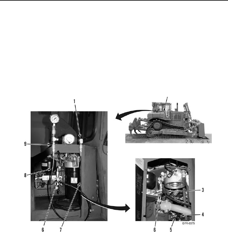
IMPLEMENT PUMP DISCHARGE TESTS CONTINUED
Low Pressure Standby Pressure Test - Continued
0033
N OT E
Transmission filter shown removed for clarity.
3. Open door (Figure 2, Item 2) (TM 5-2410-241-10).
4. Remove protective cap (Figure 2, Item 3) from fitting (Figure 2, Item 6).
5. Remove protective cap (Figure 2, Item 4) from fitting (Figure 2, Item 5).
6. Connect 177-7861 hose (Figure 2, Item 8) coming from implement pump discharge pressure port (Figure 2,
Item 9) to fitting (Figure 2, Item 6).
7. Connect 177-7862 hose (Figure 2, Item 7) coming from signal pressure port (Figure 2, Item 1) to fitting
(Figure 2, Item 5).
Figure 2. Test Equipment Installation.
0033