
TM 5-2410-241-23-1
0033
IMPLEMENT PUMP DISCHARGE TESTS CONTINUED
Margin Pressure Test and Adjustment - Continued
0033
30. Start machine and allow it to run for 15 minutes to reach normal operating temperature (TM 5-2410-241-10).
31. Ensure parking brake switch is in ON position (TM 5-2410-241-10).
32. Set machine to HIGH IDLE (RABBIT MODE) on the throttle switch (TM 5-2410-241-10).
33. Ensure blade is positioned on the ground (TM 5-2410-241-10).
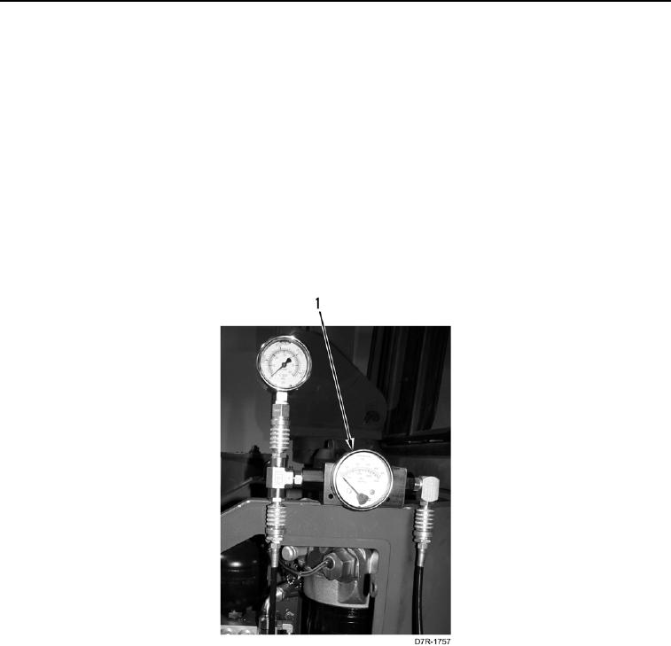
34. Move bulldozer blade control handle halfway into the RAISE position and record pressure shown on the differ-
ential pressure gauge (Figure 6, Item 1).
35. Differential pressure gauge (Figure 6, Item 1) should read 290 to 320 psi (2,000 to 2,200 kPa) while blade is in
motion.
a. If pressure is NOT within specification, repeat steps 22 through 34.
b. If pressure is within specified range, proceed to step 36.
Figure 6. Differential Pressure Gauge.
0033