
TM 5-2410-240-23-1
0030
BATTERY AND CABLES INSPECTION CONTINUED
00030
Test Step 2 - Positive Cables - Continued
00030
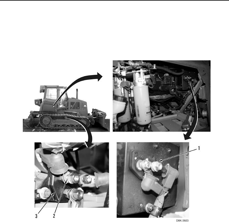
5. Using digital multimeter, measure voltage between fuse panel terminal (Figure 11, Item 1) and machine
ground. Voltage should be less than 1-Volt from value recorded in step 1.
a. If voltage is more than 1-Volt from value recorded in step 1, replace fuse panel cable (Figure 11, Item 2)
between junction box (Figure 11, Item 3) and fuse panel (Figure 11, Item 1) (WP 0205).
b. If voltage is less than 1-Volt from value recorded in step 1, proceed to next step.
Figure 11. Junction Box to Fuse Panel.
0030